Saturday, December 19, 2015

Merry Christmas and a Catch Up

Chris and I would like to wish you all a Merry Christmas and hope you have an enjoyable time with your loved ones.


Catch Up

As you will have noticed I have been tardy with my blog posts recently. I have been a bit disinterested in the layout due to the approach of Christmas, remembering back to the good times last year before 2015. I am still trying to keep myself distracted with new projects and have been finding it difficult to continue working on projects in hand. This includes the Werris Creek station building, the subject of my last post, nothing has happened.

Chris and I went to the Branchline Modellers Forum in Coffs Harbour and thoroughly enjoyed ourselves but of course it was an escape from reality, anyway enough of that.

I have been working on several 3D projects including the catch points and indicators; I have stalled here while I work out how to increase the throw from about 75 degrees to 90 degrees to spin the square indicator fully. I have had pilot versions printed in both HO and 7mm Scale (very nice in 7mm, very small in HO).

NSWGR A Frames

I have drawn up and had printed some NSWGR A Frames; now these are the stands that support and guide the point rodding from a lever frame to one or more points.

I have taken the usual couple of photos but as the prints are in the translucent Frosted Ultra Detail material from Shapeways they are difficult to get a clear image of the surface detail. Here are photos of a double A Frame in HO and a single A Frame in 7mm scale. The A Frames are still on the sprue and the point rodding is 0.5mm X 0.5mm Evergreen shaped strip for HO and a 1mm X 1mm Evergreen shaped strip for 7mm Scale.

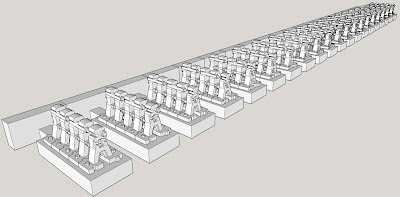
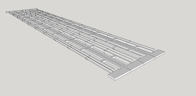
I have also included a render from the computer so that the detail can be more readily seen. Once the frames are painted the detail will be more visible (done now - see below).

HO Scale A Frames
7mm Scale A Frames
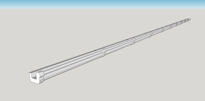
Computer Render of banks of four A Frames
I am quite happy with these and have put the HO and 7mm Scale versions on my Shapeways shop.

See my previous blog post for details of some Shapeways money saving offers over the next week.

The 1mm strip fits nicely through the 7mm Scale A Frame but the 0.5mm strip is a neat fit.

It is best to 'dry' fit the rods while the A Frames are on the sprue, then cut the A Frames away, space the A Frames on the rod(s), glue then spray paint the whole structure. Also It would be best to only make up lengths as long as the Evergreen strip, any longer and they become unwieldy when spray painting and handling them. Of course the lengths can be joined/glued together on the layout.
 
I have drawn up A Frames in 1, 2, 3, 4, 5, 6, 7 and 8 wide and they are available as a sprue of 20.

Next, I have to start drawing up the bell cranks, compensating cranks and other bits that operate the points. I have some photos and basic dimensions so only have to find the time which might not be until after Christmas.
 
While at the Branchline Forum we went to Dorrigo on the Sunday and I managed to measure the spacing of the A Frames from a lever frame to the first point near the Dorrigo Home Signal. The spacing was unusual being 7 feet give or take a few inches. The point rods were bolted together and the joints were spaced between the A frames, the rods being 14 feet long. Now these seem to be odd dimensions and all I could think of was that the rods would be carried in an S truck with the space beyond their ends in the S truck being taken up with the A Frames themselves. Who knows?
 
Here are photos of the HO and 7mm Scale A Frames. Note that the 7mm ones are just sitting next to some HO track on my layout.
 
Painted HO double A Frames with rods (not glued in place yet)

Painted 7mm Scale single A Frames with rods - Note: HO track behind
In the HO photo the observant may have noticed the wheel fitting on the bottom of the signal post, here is a photo of the A Frames and the signal.

HO A Frames and high resolution FUD signal
High Resolution 3D Printed Signal

The signal in the diorama photo is a pilot model 3D printed in the Frosted Ultra Detail (FUD) material from Shapeways. I did this to see if I could come up with a higher quality signal but also to try to keep the price as low as possible. I achieved this by producing the signal in FUD and the mechanism in White Strong and Flexible (WSF) like the signals available from my Shapeways shop. I made a shorter mechanism to use less material and a smaller machine space as Shapeways uses both of these parameters when calculating the print cost. I think that I can make a signal available for about AU$12 - AU$15 more than the WSF signals.

The signal is amazingly strong but it could break if given a quite hard knock. It is very difficult to break a piece of 2mm square FUD sprue with the fingers, well I can't actually.

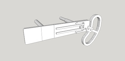
The ladder and handrails are not printed and will need to be supplied by the purchaser. Handrails can be made from brass wire and I am developing a handrail bending jig for bracket signals. This jig can be used to make wire handrails to replace the printed WSF original ones, similarly an etched brass ladder can be used to replaced the WSF printed ladder on the original signals.

The signal in the photo above has an etched brass ladder from Peter Boorman's Workshop but other ladders can be used including Kerroby and Keiran Ryan's etched ones. I am going to add the cast iron ladder support structure at the base of the prototype ladder to the drawing.

Signal Ladder Base Support Casting
Here are some computer renders showing the signal and detail (some details are so small on the print that you almost need a magnifying glass). The detail parts have been added to the signal to eliminate the Shapeways US$5 handling charge per item to assist in lowering the final price. The structure above the detail parts sprue box is there to stop warping of the signal post during post-printing clean up. The FUD prints are heated to remove a wax used to support overhangs in the model. Of course this adds to the cost. I could remove this structure and the modeller could use hot water to straighten the post but I think that is asking for issues. Prints could be cheaper without the protective 'boxes' and structural elements but the result wouldn't be good. If a part breaks off the print is failed and too many failures and Shapeways withdraws the item from the shop.


Note the improved detail, various bolts and the cast on finial

39 inch Signal Arm with added detail
Signal Wire Pulley - At base of post.
My question though is: "Is it worth redrawing the other 19 signals in my WSF range so that the signals can be available in both WSF and FUD?"

Some feedback would be useful.

Monday, November 9, 2015

A Bit More Architecture - Werris Creek Station Building Again

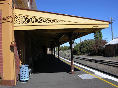
A while ago I tried to restart construction of the Werris Creek station building for Ron Cunningham's Werris Creek layout and realised that I hadn't etched enough awning post cast iron support brackets Also, given that I had etched them at home the consistency of the etches wasn't that good.

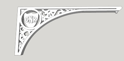
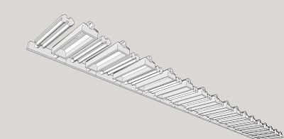
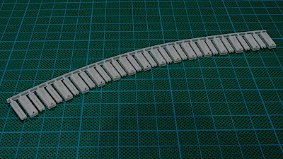
I sat down at the computer, fired up Sketchup and spent several hours drawing up the bracket. The following photo of the brackets and a screen grab show the result. The brackets now had some thickness and edge flanges around the fancy bits, much better. Due to wall thickness design minimums for the Frosted Ultra Detail material I had to do some creative drawing to get more of an impression in places by impressing some detail rather than cutting through. Over all, although it isn't as fine or airy I was very happy with the resulting 3D model. The GNR didn't come out and this was probably because the height of the letters wasn't enough and the height is restricted as there is a ratio of height to width where the letters would become a wall and they would fail the minimum wall thickness test.


Rear of the brackets showing some fine lines caused by the support material used in the printing process
Other side of brackets, nice and smooth
I had originally etched the cast iron detail in the end of the awning as well so I decided to give it a go as well and this one I am very pleased with as being larger the wall thickness design minimum wasn't a real issue.
 
 
The lower awning end is for the awning on the other platform
3D printed Frosted Ultra Detail awning end
As can be seen, by using 3D printing I was able to also make the whole awning end rather than having to construct it from Evergreen polystyrene strips and shapes.

I am now at the stage with the build where I can offer the awning up to the building although I still have to add the smaller downpipes and scuppers that I had to rescale before I can fix the awning permanently.

I haven't quite finished the awning itself as I still have to fit the corrugated iron and there are 4 foot (1200mm) single fluorescent lights on the awning rafters between each post as shown in this photo.


So here we have some HO single tube fluorescents that will take a 603 Cool White SMD LED (with leads). The LED fits into a hole in the middle of the base and the wires exit the end closest to the wall to be connected to a resistor and power inside the building. The light base will be painted black and then white to try to restrict the LED light to just the tube but I am sure that it will mainly be in the centre of the tube. I am not sure how else it could be done given the restriction of the size of the base and the minimum wall design thickness.

Top

Base showing LED location and wire slot
But, there is more.

Mounted on the building as well as scattered around the platform on posts are some hooded double fluorescent lights so I have done these as well.


Here are screen grabs of the top and the bottom of the lights. The double fluorescents go inside the hood with the 603 SMD Cool White LED placed inside and the wires threaded through the hole in the end of the hood. The hole in the end of the hood and the wire slot are large enough to have a piece of 1mm plastic rod or 0.035" phosphor bronze wire (be careful here don't damage the LED wires) inserted to be used as the tubular mounting shown in the above photos.

Top
Base

Here is a photo of the 3D print, as the Frosted Ultra Detail (FUD) is translucent prints are very hard to photograph.


Well, the above have been some of the distractions I have been involved with trying to overcome the loss of our beautiful daughter earlier this year. The problem I have is completing things but I am sure that it will all come together.

On another architectural note, a comment was posted on my recent architectural post asking about cast iron lace work and panels for terrace buildings, pubs, etc. I have had these on my list for a while and do have some photos/artwork that I can work with. The problem is that a lot of the lace work is very fine and the minimum wall thickness issue will raise its head. So only certain designs will probably work. These will take some time as the conversion/tracing of the lace work and the adjustment for wall thickness is quite involved, there is also the question of how long a length of lace work panels, etc. should be designed.


Monday, November 2, 2015

A Little Bit of Architecture

OK, not architecture in terms of whole buildings but a few bits I have been working on.

A while back I was in need of distraction to keep my mind from other things and I find that the problem solving that is required for drawing up 3D items is just the thing to keep the mind occupied.

I decided that I would have a go at drawing up some corrugated iron, firstly to see if it could be done effectively and also out of interest to see how much it might cost to have printed.

I managed to track down some cross-section drawings of  'standard' corrugated iron and using this as a starting point I imported the line drawing into Sketchup as a JPG image. I then traced the cross-section and proceeded to turn it into a 3D representation within the limits of Shapeways Frosted Ultra Detail material. I had decided that the White Strong and Flexible material wouldn't give a nice smooth surface and anyway the wall thickness design minimum precluded it from the project.

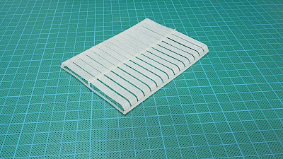
Here is a picture of a print that I have had done. I had this printed to see what it looked like and to get an idea of the price, unfortunately nice as it is the price is expensive compared to available HO corrugated iron. The sheets are 10 feet long and 22 1/2 inches wide which is the visible size of a sheet of iron that has a one and a half corrugation overlap. The idea is that each sheet will but against the next on a suitable modelled timber framework or sheet of plastic and the edges of the sheets will be seen as the joint between sheets. The printed sheets are only 0.42mm thick.
 

I have since added more supporting sprue instead of the single sprue down the centre. This is to ensure that nothing will be broken off in the cleaning process after printing. The problem is that Shapeways staff don't know what a particular print is so if something breaks off, the print is rejected even if it doesn't matter to the modeller. Of course some printed bits left loose after the cleaning can't readily be identified with a particular print order.

Since the print was acceptable I then moved onto something that I had been thinking about for years, bull nose corrugated iron. Bull nose is a challenge due to the difficulty of rolling the curve to the right radius and to do so without putting a kink in the corrugations. It was also a challenge to draw, here is the result.


Now, where to from here? I was telling a friend about what I had been up to when he asked, "What about decent guttering?" I promised that I would give it a go and send him some, so this was next. Back to find a  suitable gutter cross-section from years ago (1930's, 40's, 50's, 60's, 70's, etc.). I knew that wall studs and roof rafters were spaced at 18 inches (450mm) in older houses and that gutter support brackets were usually placed on every second rafter end so this is what I drew up.


 And I then added sprues to give 4 x 30 foot lengths for printing.


Here is a photo of the printed gutter which I have darkened in an attempt to make the support bracket detail, etc. show better. The guttering print price looks good.


I am currently waiting on a print of a corrugated water tank which price wise at least is viable, here is a computer render of the tank and it has the correct corrugation cross-section.
Well, that is about where I am at with these items and I have decided that I will put them all on my Shapeways Signals Branch shop, someone might be rich enough to want to use the corrugated iron sheets, who knows. I am also making them available with the long term hope that the cost of printing will come down so that I can reduce the price.

Now I just have to find a nice building to make so that I can use these bits.

Wednesday, October 7, 2015

A Few Photos from the AMRA Liverpool Exhibition

Here are some photos I took last weekend. They do not represent every layout or my interpretation of the best layout(s). They were taken just because a particular scene caught my eye.

Please note that the photos are not up to my usual standard as I used a small pocket size camera as dragging a tripod around to take good photos is just impossible at the exhibition.

I hope that you see something to enjoy.

BINALONG


MUNGO SCOTT


ILLABO


YENDYS


PENROSE GORGE - WOLGAN VALLEY


A small amount of photo shopping was done to extend backscenes upwards and eliminate backscene joins and marks, etc.

Of course I would probably have taken more but I had too good a time catching up with many modellers. If I didn't catch up with you then maybe next time.


Monday, September 28, 2015

Catch Point and Indicator Update

I haven't had a post for a few weeks as Chris had a sudden gall bladder operation after two attacks in two days and last Monday I had a cataract operation on my eye that was infected when I had the shingles in March of 2013. The eye drops I had to take to clear up the infection in the eye ultimately gave me a cataract. So for some time I have been working with basically one eye shut to eliminate the blur. It was OK for driving etc. but not for reading, the computer and modelling. I now have to wait for about 6 weeks for the eye to settle down before I get my glasses sorted. So I still have dodgy vision for modelling, etc. but not as bad as before.

Anyway, my Shapeways 3D prints of the catch points (White Strong and Flexible) and the indicators (Frosted Ultra Detail) turned up last week and I have been assembling them to see if I have designed them well enough to have them actually work.

OK, well the catch point needs to be amended as the dog spikes are too fragile and I lost a number of them while inserting the rail. The rail was Peco Code 75 flat bottomed. I haven't tried MicroEngineering Code 70 as yet but it does have a similar base width so I would expect a similar result. If you get a catch point when I put them on my Shapeways Shop then don't paint the sleepers first, it just makes it harder to insert the rails and I lost a few more dog spikes doing this.

I have beefed up the dog spikes by 10% and raised them slightly to give better clearance for the angle of the rail bottom flange area but there is a limit before the spike heads will be hit by the wheel flanges. So far they are clear of 88 and 110 wheel flanges.

Printed Left and Right Catch Points as received
The catch point indicators were printed in Frosted Ultra Detail which gives nice detail but can have occasional slightly rough surface areas which is due to a support material used during printing. As usual, I used a rinse in acetone for 1 - 2 minutes to clean any oily material that is used to clean away the support material.

Catch Point Indicators - Brightness and Contrast adjusted to try to show the detail
As I mentioned above I inserted some rail into the sleepers to test the fit but also to test the gauge which was successful.

Check of rail gauge - Lower rail temporarily fitted
The three items attached to the sleepers are from left to right, a wedge that is fitted inside the lower rail to raise the wheels up and over the rail and two alternate sleeper extensions for mounting the indicator on. The sleepers plug into the ends of the main sleepers around the area of the point blade.

One indicator set clipped from the main sprue with most of the sprues cut away to assist with painting access
The rails were cut to size, inserted and glued in place with Super Glue (ACC). The point blade was filed to a taper and then cut to length. he main rail was filed away to accommodate the point blade where they meet.A MicroEngineering rail joiner was cut in half with a cutting disc in a motor tool. The joiner was held in a pair of pliers and it was opened up by inserting a scrap piece of rail into tit before it was carefully pushed onto the end of the rail in the catch point. Another piece of rail had one end filed to an angle to meet the rail before being inserted into the angled sleepers.

Part assembled catch point with an indicator
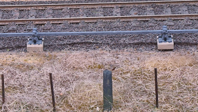
Here are several photos showing the catch point with indicator in a typical position in Bylong yard. Catch points were placed where a siding met the main line so that parked wagons would not foul the main if the rolled away. This catch point would need to be curved to fit in this location so I will build one from the new design when I get it back from printing. The catch points will be able to be curved by clipping away sections of the web between the sleepers on each side of the rails much as is done on flex commercial track. This is one advantage of the White Strong and Flexible material, the other is cost as the catch point would be exorbitantly expensive in the Frosted Ultra Detail material, 'horses for courses'.

Overall view of the location - A lit Clearance Post can be seen on the right
A closer view
A close up view of the indicator - The square section rotates to the other aspect (arrow)
Unfortunately I didn't design the operating component of the rotating indicator head well, it won't turn the head fully. It is amazing how it can be difficult to envisage the way something should work when designing in 3D but how obvious it is when you hold the item in your hand. I now know what I have to do to make the indicator aspects move through 90 degrees when the point blade moves, or I hope so.

Another set of prints will be ordered when I finish the design changes. I hope that this indicator can be lit from below the baseboard by an LED in a hole drilled from below but I will only find out once I try it. The light will have to go vertical (easy) then be bright enough to reflect out sideways  through the pivot, into the head section and out the small red lens and the arrow area. Fingers crossed on this one.

Finally, here is the NSWGR plan again.

NSWGR Standard Catch Point - 1936