
I hope everyone has a safe and enjoyable Christmas and New Year.

I hope everyone has a safe and enjoyable Christmas and New Year.
Several years ago the layout gained a mysterious short circuit even though I hadn't been doing any wiring or trackwork recently. After a lot of searching under the layout and checking the track for closed rail gaps, I called in the big gun, Marcus Amman.
Marcus spent an afternoon with me checking all the same things and we still came up with nothing. At this point, it was decided that I needed to replace the NCE EB3 circuit breaker board as the EB3 boards were known to be a bit flaky. So, three NCE EB1 circuit breakers were bought and temporarily installed in the wiring. Now what I mean by temporary is that they just hung down below the layout suspended by the wiring to them. This situation stayed that way until about a month ago when I decided it was time to fix the mess.
I won't go into a too long-winded explanation of what I did so I will present the photo below and it will become self-evident. The EB1s are mounted on the perspex panel with 3D printed stand-offs. The stand-offs were 3D printed because we were in COVID-19 lockdown and I didn't want to do Click and Collect at Jaycar where there is a whole range of different sizes. Longer stand-offs were also printed to mount the panel on the layout fascia. The lit red LEDs on each EB1 board indicate that all is well.

Now, I should mention that somewhere along this journey when the EB3 board was replaced by the EB1s the short circuit disappeared and hasn't shown up again.
I should also state that the mainline was divided into two districts and the Cassilis branch was the third district. The mainline was divided at Coxs Gap loop but for years the two mainline districts would shut down when there was a short in either, I obviously had a sneak path in the track wiring. I searched for this for a long time and eventually accepted that this was just the way it is. Of course, when doing something totally unrelated under Coxs Gap loop I found some wiring that went from one end of the mainline outside the loop to the other end, it was tucked up behind some layout framework. A quick snip and all was well with the BYLONG world.
In the photo above a toggle switch and a 5 Amp ammeter can be seen. This measures the total amperage drawn by the layout when operating. The toggle switch is to cut the ammeter out of the power to the track when not reading as it uses some voltage. It is turned on when needed to check the current draw.
I am very pleased with the installation and it has taken away my concerns about those EB1s hanging in the wiring, also they were not very professional looking.
As we all do, the search for a good and easy way to clean track can cause us to try all sorts of things. Of course, one way is to use the Peco track rubber or other brand, another is to use what used to be known as an ink rubber (eraser), a slight abrasive was bonded in the rubber. I have noticed that these are very hard to get anymore which is a pity as they were better than the Peco rubber. I am not going to get into the argument about the abrasive rubbers scratching the rail head as my track is long past protecting from that potential issue.
One thing I have always done is to use a 38mm paintbrush and drag it along the track at about 45 degrees to remove dust which I believe is a major part of dirty track. Combine dust with some conductivity fluids and you make the grey stuff that builds up on the wheels. Anyway, that's my theory. The dust by itself can also cause erratic power pick up and running. I will use the brush if I haven't run the layout for a few weeks.
In regards to conductivity, I started decades ago by using CRC 2-26, an electrical conductivity spray, this certainly works well but must be applied sparingly and away from grades. I applied it to about 50cm of each rail on level track in several places around the layout as well as on the point blade and stock rail contact areas of points. I did find many years later that it can build up to a slightly sticky form at the point blade contact areas and start to restrict blade movement. This was rectified with an application of enamel paint thinner on a cotton pipe cleaner. This is how I enhanced conductivity until I started looking for other ways several years ago.
The next trials involved the use of graphite pencil sticks which seemed to work well but also had to be kept away from the layout grades. These can be found in art supply shops.
My latest efforts involve a geared motor rotating a cleaning pad against the rail tops. This motor is built into an NSWGR 48 Class HO model that runs as a dummy with another diesel locomotive, usually a Trainorama 44 Class. Behind the diesel locomotives are several wagons that have other track wiping and cleaning fittings.
Here are some photographs that show what I mean.


The cork disc and the cork on the Dust Monkey have a small amount of CRC 2-26 electrical conductivity fluid applied to them before operating. The CRC 2-26 can also be applied to the rails in a number of places around the layout to rejuvenate the cork. Any buildup of the grey dirt from the track can be cleaned from the cork carefully with some enamel thinner. Be careful not to saturate the cork with the thinner as it may cause the glue holding the cork on the plastic to soften. I use a cotton pipe cleaner to clean the cork.
The 48 Class has a piece of grey sponge mounted behind the leading cowcatcher to wipe the dust away before it can get on the locomotive's wheels and cause problems. I am still looking for a small brush arrangement to replace the foam.
The motor that spins the cork disc is a 1000 rpm geared 12volt DC motor that can be found here (at the time of this post of course):
Or
The body of the 48 Class is an old Trax body and the chassis of the 48 Class is made of several 3D prints. The non-powered 48 Class bogies are from the early Trax 48 Class and I have used two of them. They clip into the 3D printed chassis the same as they did on one end of the Trax 48 Class. It was lucky that I kept the Trax 48 Class chassis' when I made new mechanisms some time ago. See the blog post here.
The prints were done on a 3D filament printer except for the fuel tanks which were done on a resin printer. The fuel tanks might work on a filament printer with appropriate orientation and supports.
If anyone is interested and has an old Trax 48 Class body and a couple of the non-powered Trax 48 Class bogies then here are the STL files of the chassis parts and the fuel tank side (two required).
The chassis parts were printed flat on the bed of the filament 3D printer.
Of course the adventurous could always design and print the bogies and use the white metal bogie side frames if they are still available.

 |
| Various trial materials were used on the disc - 2 types of material, cork, 2000 grit Wet and Dry and the last one has glue on it from a covering I removed. |
 |
| Under chassis view showing a piece of foam that exerts a slight downward pressure on the disc. |

 |
| View showing motor sitting in the square box mounting. |
 |
| 1000rpm 12 volt motor |
If your diesels are having intermittent power pick up issues then have a look at this earlier post where I put forward a theory about it and solve it with some easily fitted power pickups.
Two posts ago I installed a triple bracket signal to act as the Home for Wollar station and yard. As I had some access difficulties if I wanted to install two normal bracket signals, I opted for the triple bracket.
The post was mainly about the small sleeper built retaining wall that I needed to make and install to retain the existing scenery where the triple bracket had to go.
This time I want to show what I did about controlling the triple bracket and also how I solved the visibility issue. The triple bracket was placed on the curve leading into Wollar and as such the arms were not easily visible to determine which track was set up for the train entering the yard.
As mentioned in the earlier post I cut the triple bellcrank style mechanism away and replaced it with one of my triple linear servo mechanisms by glueing it to the underside of the existing triple bracket base.
I then set up three Tam Valley Depot Singlet II servo control boards where I could access them from the front of the layout.
I extended a LED from each Singlet II to the front of the layout fascia and mounted the LEDs in a 3D printed box that showed which track each LED related to. The LEDs are bi-colour so show red or green depending on the signal arm position.
Here is the box with LEDs in place, working and showing green for the Main line.

Note the Accessory numbers A54, A55 and A56 as well as the L, M and BP written on the Singlet IIs with a white fine point paint pen. The L stands for Loop, the M stands for Main and the BP stands for the Back Platform track. Strangely, the Back Platform track is actually at the front of the layout. It is the track that the Cassilis branch trains arrive and depart from.
At the moment the triple signals can be operated by the buttons on the Singlet II control board or by accessory commands. The intent is to use an NCE Mini-Panel to change the appropriate signal arms based on the point levers (control panel switches). There is an Accept lever (switch) that can put all triple bracket arms to Stop.
So, the points will be set first, then the Accept lever will be set to allow entry and the appropriate signal arm will change to clear. The responding LED will show Green on the indicator box on the layout fascia.
Incidentally, the gap between the inner layout frame with the Singlet IIs and the outer piece of layout frame where the indicator box is mounted can now be filled with a piece of baseboard and the scenery will be extended down from the road to the front of the layout.
I have a small NSWGR signal box meant for platforms on my Signals Branch Shapeways shop. The signal box is described as a 'Cheap Platform Signal Box'and one look at it and you can see why the NSWGR accountants must have loved it.
Links are here for those who may be interested.
Cheap Platform Signal Box available in Versatile Plastic or Fine Detail Plastic.
I have several of these signal boxes and I chose a Shapeways Versatile Plastic version to use as the basis for a junction signal box for the coal mine branch near Wollar. Now, as this is a platform version I needed to build a supporting structure for it.
Once again, I turned to my computer and ran Sketchup to design a corrugated iron lower supporting section. As part of the build, I also designed a flat base for the signal box to sit on. Extra parts were designed as well, these being a platform and steps, bellcrank and signal wire wheels for the area between the signal box and the track. I already had a small water tank designed so this came into the build but I needed a different downpipe from the gutter to the water tank and a water tank tap as well.
The corrugated iron support structure and the base were printed in PLA on my filament printer and the other small parts listed above were printed on my resin DLP printer.
Here are a few photos of the finished signal box. Overall I am quite happy with it and it is now put in place at the junction with appropriate scenery materials blending it into the scene.


Back again!
When I first started drawing 3D signals that were available through my Shapeways Signals Branch shop the range was initially in the sintered nylon powder previously called White Strong and Flexible and now called Versatile Plastic by Shapeways. The signal detail parts were in Fine Detail Plastic. At the time I bought enough signals to signal my BYLONG layout. It was later that I redrew the signals for the Fine Detail Plastic and then Lost Wax Brass. So, I have been building my signals but upgrading them with fine ladders and wire handrails, etc. They don't look too bad at all, at least from a normal viewing distance.
I have been working on a triple bracket lower quadrant signal for my Wollar station yard on and off for some time in between making brass NSWGR signals for other modellers and I recently decided I had better finish it.


Here are some recent signals made from my range of locally produced lost wax brass signals.
Contact me by email at rpilgrim@bigpond.net.au if you wish to know more information about my range of signals or about ordering from my range, either signal kits or made up signals.
I cut off the existing crank-style mechanism and replaced it with a triple linear servo base as the under baseboard location of the signal was difficult to access. The linear servos were being driven by Tam Valley Singlet II servo boards that also have a DCC accessory decoder. The Singlet II boards were going to be mounted just under the front of the layout for easy access with one of the LEDs on each board being extended to the fascia. The reason for the visible LEDs was to show the position of the three arms as the actual signal could only be seen from the side. In doing this I also had to source some longer servo cables which I did through the Model Railroad Craftsman at Blacktown NSW.
Now, the location for the signal required the removal of some scenery from a low embankment in a box shape so I decided to draw up and 3D print a three-sided retaining wall made of sleepers and rail.

I had previously drawn a long retaining wall made of sleepers and rail for my layout so I modified that to suit.
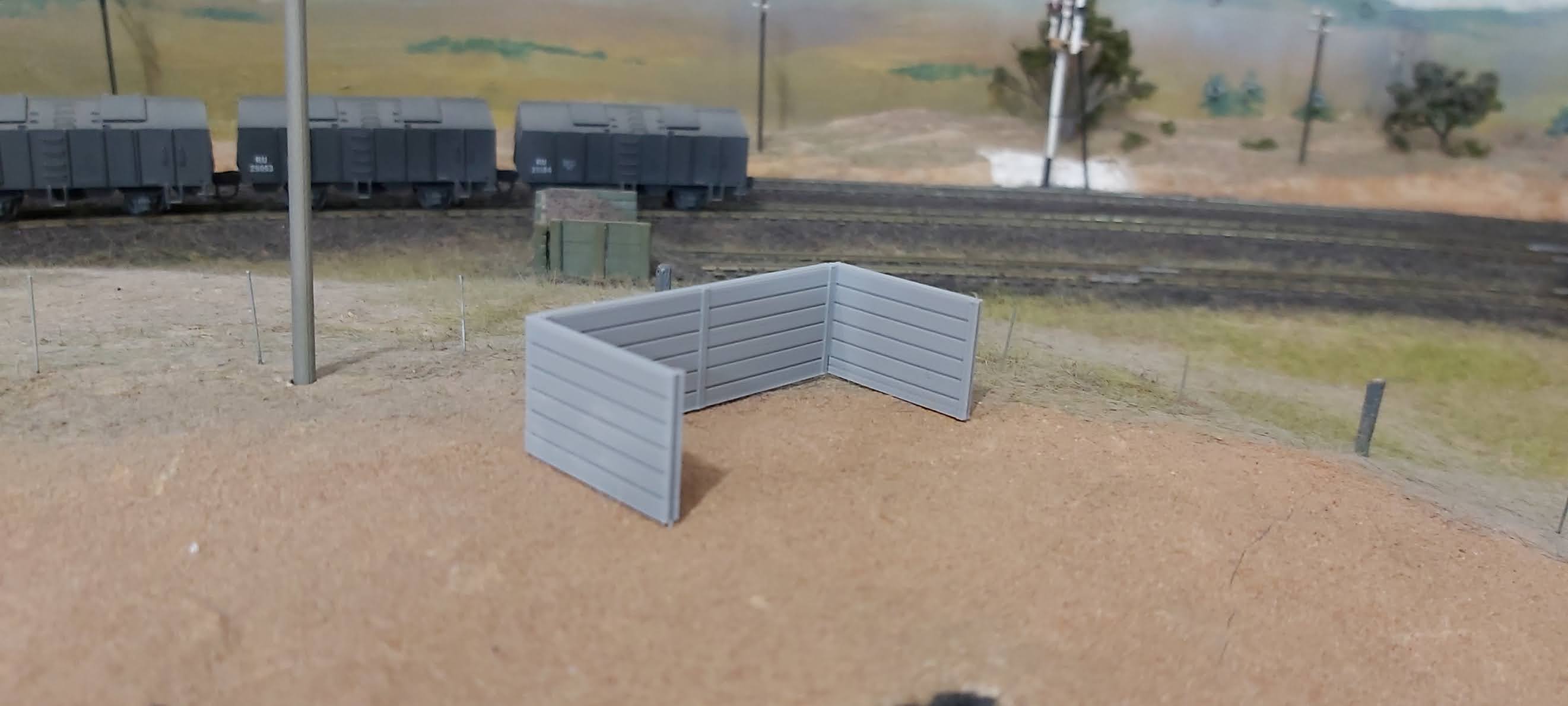
Here is the retaining wall temporarily in place after trimming the scenery to size.

And here is the final placement of the retaining wall after painting the vertical rails with an old rust colour and using black powder on the grey plastic for the wood sleepers.

A nice afternoon's work I think.
The signal has had the throw of the signal arms adjusted and set by the Tam Valley Singlet II boards and it has been screwed in place. Unfortunately though as can be seen from the last photo above, I have to remove it and glue the large painted cast-iron brackets under the bracket platform, too excited to get it in place for sure.
A few weeks ago my BYLONG layout had an interesting visitor, the engineering sample of the Casula Hobbies Z19.

The model ran very smoothly and is geared down to a very respectable low top speed typical of the prototype. I didn't measure the speed but it appears to be no more than about a scale 40 mph. Slow speed running at DCC speed step one was impressive as well. The detail level is fantastic!
I have the Baldwin tender 1957 with cowcatcher and sound on order for my Cassilis branch line. The branch line is not fenced so the cowcatcher is needed. My Wombat C30T is the current branch locomotive but it doesn't have a cowcatcher, something I may have to remedy in the future.


