Tuesday, November 25, 2008

A Major Change to BYLONG


For those who have been wondering about the hint I made a few weeks ago ("There was movement at the station"), I have changed the layout, the upper staging yard has been picked up, rotated through 180 degrees and is now located over the Bylong tunnel and Cox's Gap cliffs.


A 1 in 40 grade now starts just west of Wollar, near the bottom left of the photo, crosses the garage doors above Bylong and climbs to the top staging yard.

More banking and double heading out of Wollar loco depot!!!

At the start of the 1 in 40 grade there is a junction of the new 40' (12 metre) branch line which proceeds across the roller doors and then under the upper staging to then swing through a 180 degree curve to the branch terminus (where the upper staging was). Only about 3 feet (1 metre) of the branch line is hidden trackage.
If you look carefully you will notice that the branch has a roller coaster in it. I decided to add this feature as I have seen lines that follow the country side rather than just cut through it. The small 'hill' is approximately 435 feet long and is only about 4'6" high, about 1 in 60 each way to the crest. I will be interested to see how this looks once the scenery is done as it looks odd at the moment.

The branch terminus will be 12' x 2' and at the moment I haven't decided on the track layout but it will have a turntable, wheat silo and the usual goods shed, loading ramp, etc. I have about eight prototype station plans to choose from currently and most seem to have seven points.
Although you can't see it in the photo because of the lights, the area above the cliffs where the branch line runs will be sceniced as well even though only about 4" high.

This branch line is the culmination of several years thought trying to work out how to fit a branch in. Of course the idea finally came and it was all worked out in about 10 minutes of measuring, although it took me about another month of pondering before I started.


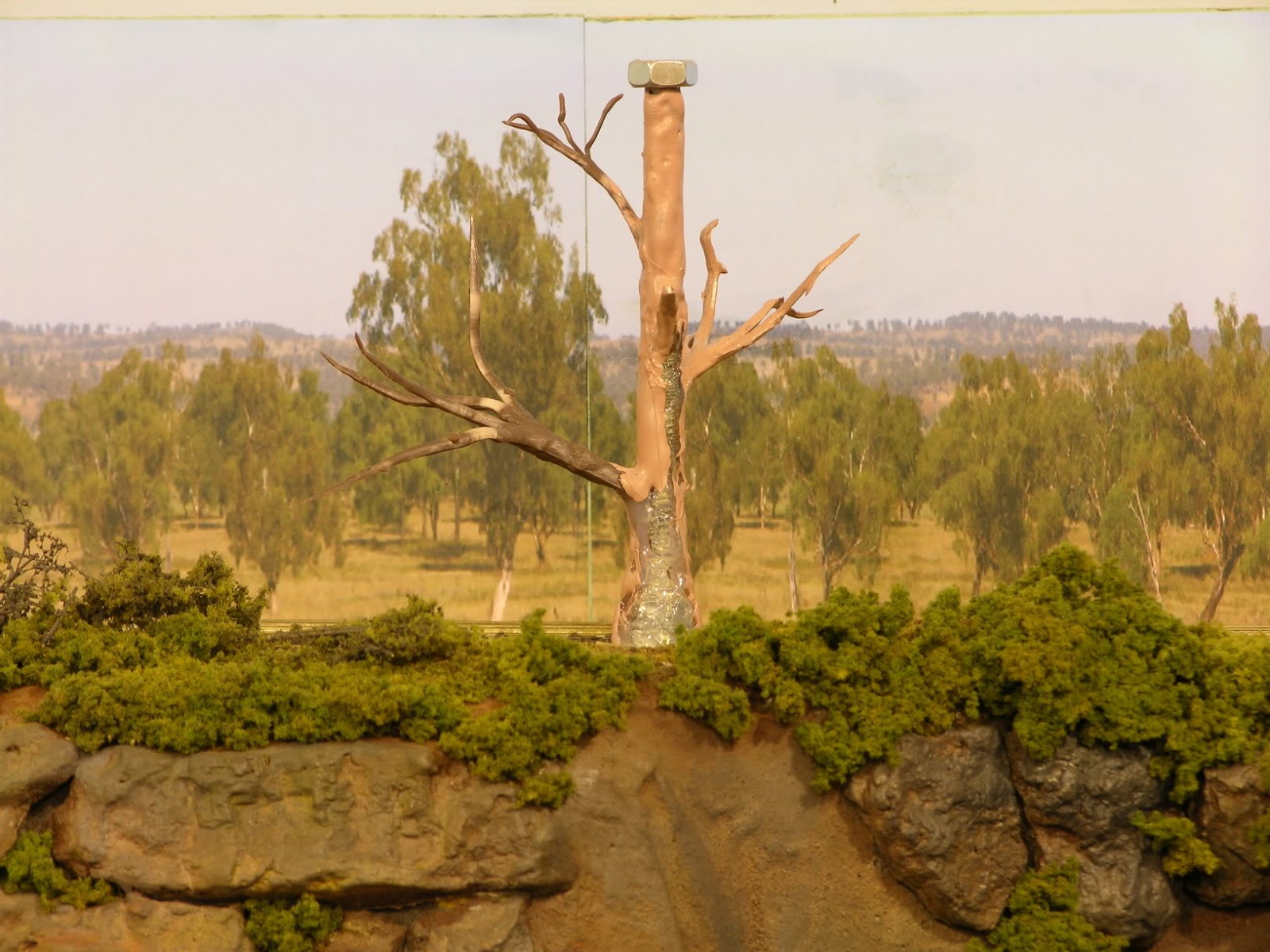
The tree upper level support (as mentioned on my blog a few weeks ago) can be seen in the photo and the branch line is running just behind it and in front of the printed backscene. The upper level staging is supported at each end and in the middle, by the tree.

Sunday, November 9, 2008

Second Set of Scalpel Saw Blades


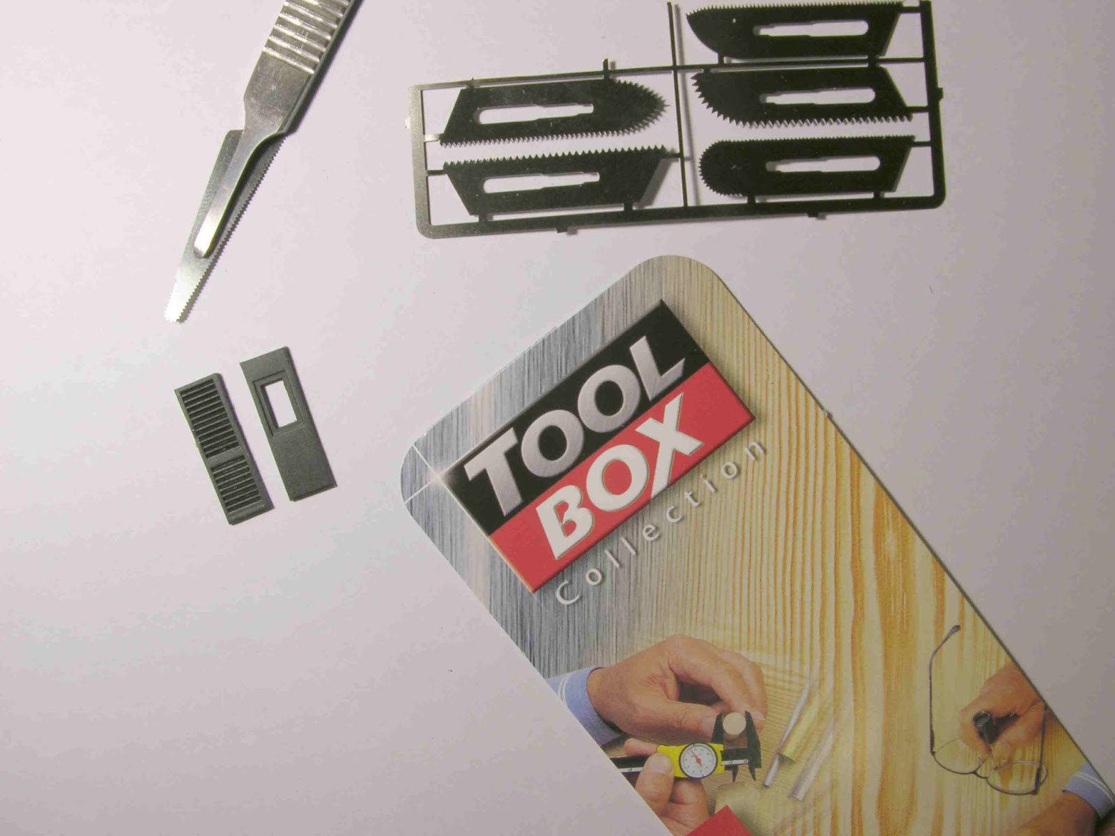
Here is a second set of saw blades, this time there are two longer blades.

The packet states that they are 0.12mm thick but they are actually 0.24 mm thick, the same as the other set.

The price for the blades by themselves is $20.30.

Wednesday, November 5, 2008

I Found a New Tool


I am a person who really is a collector of small modelling tools, show me some small obscure tool and I am likely to buy it just in case.
I found this new tool, a scalpel saw at the Auburn Bunnings hardware store here in Sydney. This line of hobby tools had been mentioned a couple of times on the Aus_Model_Rail Yahoo group so I decided on Monday to go and see what was on offer.
As you can see in the photo above the tool is a scalpel handle that takes very fine saw blades. The blades are etched in stainless steel and are 0.24mm thick. There were several sets available; one with saw blades about twice the length of those shown here.
I decided on the short version as I wasn't sure how strong they would be. Well, I was pleasantly surprised, as you can see I have cut the doors from a Trax MHG. This took seven minutes to do and the blade removed the door without taking any part of the doors with it. That is the saw was the width of the moulded crack between the doors.
The blades are etched into a sheet and they must be cut from the etch.
Do not use tin snips as you will wreck the blade edges, the stainless is very hard. I used a thin stone cut off disc in a motor tool but be very careful and go at it slowly at the slowest speed possible, you don't want to bend the blades and do use safety glasses or goggles.
Now for the price .... $30.70, a bit of an ouch and I had my fingers crossed but I am very happy with the purchase.


Friday, October 31, 2008

Shorter Trainorama C32 Couplers


For those who have larger radius curves the supplied Trainorama C32 class couplers are too long leaving a large gap between the locomotive and the first carriage.

The supplied coupler is a work of art but there is no way it can be shortened so here is how I managed to do it.

Step 1

I found that there was just enough 'meat' ahead of the pivot hole in a long shank KD 156 coupler to drill a No.50 hole for the C32 coupler pivot screw and file the rear and two sides to match the supplied C32 Trainorama coupler.

To drill the hole I first used a scriber to make a centre mark for the drilling. You will have to mark this by eye as it is too small to try to measure and mark it.

Next I used a No.57 drill in a pin vice to drill the first hole then made it progressively larger with a No.55, No.53, No.52, No.51 and finally No.50 drill. It is best to do it this way as the drill can easily bite into the die cast metal and jam.


Step 2

The next step is to carefully cut the rear hole section of the coupler away. I used a jewellers saw to make the first cut into the hole, this then allowed me to use a pair of sharp transistor wire cutters to snip away the rest. The first cut will allow the metal to be cut away without stressing the drilled area.

Finally I used a fine jewelers file to file the remaining curved section of the original pivot hole at the rear of the new hole away until it just disappeared, this formed the rear face of the coupler.

I then filed the two sides to the same slight angle as the sides of the C32 coupler end, also filing the corners with the same slight curve.


Step 3


I now mounted the coupler.

I managed to lose one of the two small coupler mounting screws and guess which screw isn't in the bag of spares!

I think I may just align it and put a tiny spot of glue on the screw hole if Trainorama can't supply a replacement, hopefully they can.

As you can see by the photo above I still hadn't adjusted the droop of the coupler

I found that I had filed the back just a little too much and as a result the coupler doesn't stay centred but will swing back when pushed sideways, so I suggest you go slowly and try a couple of trial fits until you are happy.

Layout Trials

I have successfully pushed and pulled some 72'6" passenger cars around 30" radius curves, up and down 1 in 40 grades. On the inner side of the curve there was about 1mm between the buffer heads.

Now, to do another for the tender and perhaps have another go at the front one.
Well, that's about it, so have a go, it isn't hard at all.

Sunday, October 19, 2008

There was movement at the station ......


For those who have been following this blog I give you something to ponder.

The first picture is of an upper layout level support made from a piece of 1/4" threaded rod. The branches are Woodland Scenics and are glued to the trunk with hot glue. I was going to use 'No More Gaps' a water based flexible crack filler but when I was gluing the branches on I just kept going. It worked fairly well. The tree is part painted with water based house paint from those little sample pots, very useful.

The final photo shows the finished support. The trunk has extra colours added using pastels and the foliage is light green Woodland Scenics foliage.

I will post some more when I move this little project along a bit further.

What I can say is that it will add a another level of operation to the layout, sorry for the pun.

Saturday, October 4, 2008

The Area I Am Modelling


The type of landscape I am trying to create, rolling hills to tree covered sandstone mountains.

The 48 class diesels are from a later period than I am modelling.

Photo by Chris Nelson - with thanks (see comments).