
Lighting for this area was done using compact fluorescent lights fitted into the frame of the upper level. Kerrabee however was a different matter. Because of the way that the outside of the teardrop had been constructed back in the 1980's I wasn't able to do the same and was forced to put the compact fluorescents above and behind the top of the low back scene which gave poor uneven light at best. A further issue was that I was not comfortable with 240 volts wiring under the layout as I had previously used 240 volt figure of eight wire for point motor power. I had used red Dymo tape to mark the 240 volt wiring about every twelve inches or so but it was still a danger.
Some time ago Bob Lynch had installed some 5 metre strings of LEDs on a lower level of his layout and also Ron Cunningham's Werris Creek, this gave me food for thought. A few weeks ago while pondering over the issue I had an idea on what to do. It was found that the combination of a strip of cool white and a strip of warm white gave plenty of light for photography along with good colour rendition, not perfect but unfortunately there doesn't seem to be 'natural' LEDs available.
The following photos show the various stages of the reconstruction of the outer part of the upper level to accommodate a higher back scene and LED lighting. The secret was the ability to put outrigger supports screwed to the rising grade supports of the upper level

The existing teardrop before reconstruction, note that the upper level only partly covers the lower level and also the depth of the upper valance.

Upper level valance and scenery removed exposing the upper level rising grading support structure.

Lower back scene extended vertically and upper supports in place which gradually increased the gap between the lower and upper levels. I considered removing the short lower back scene but I had nailed and glued it to the upper rising grade supports, hence the addition of a strip on the top of the existing back scene. This was achieved by first attaching small tabs of 3mm MDF every 4 inches or so with PVA glue held in place with cloths pegs. The additional back scene was then cut, glue applied on tabs and the top edge of the lower back scene, nailed at one end and carefully wrapped and tacked in place. The join was then filled with Spakfilla, mostly successfully but the join can be seen here and there. I made and screwed in place a small removable section of back scene for access to a point motor and servo motors for the bracket signal at the colliery junction.

Lower back scene sky painted and upper valance in place and painted black. I managed to cut down and reuse the old upper level valance which was still in a nice curve.

Fitting and testing LED lighting was then carried out. The LED strips come with self adhesive on the back so I painted the inside lower 20mm of the upper valance with semi-gloss paint to enhance the bond. The strips were attached around the bottom edge of the valance one above and hard up against the other. Although not shown in the photo the underside of the outer end of the outrigger frame extension was tapered upwards to make room for the LED strips to pass under and to minimise the height of the valance to optimise the viewing height of the lower level. Unfortunately the next morning I found that one strip had fallen off so I used some Selleys water based Kwik Grip to glue the strip back. I have since noted that the strips tend to pop off the valance in short 25 - 50mm sections here and there and I will watch this before the top level scenery is done. If it gets worse I will begin a process of using the Kwik Grip to bond these small sections until it stops. My advice is to apply the strips to a gloss painted surface and to use contact adhesive as well, you have to let the contact adhesive dry then apply the strips.
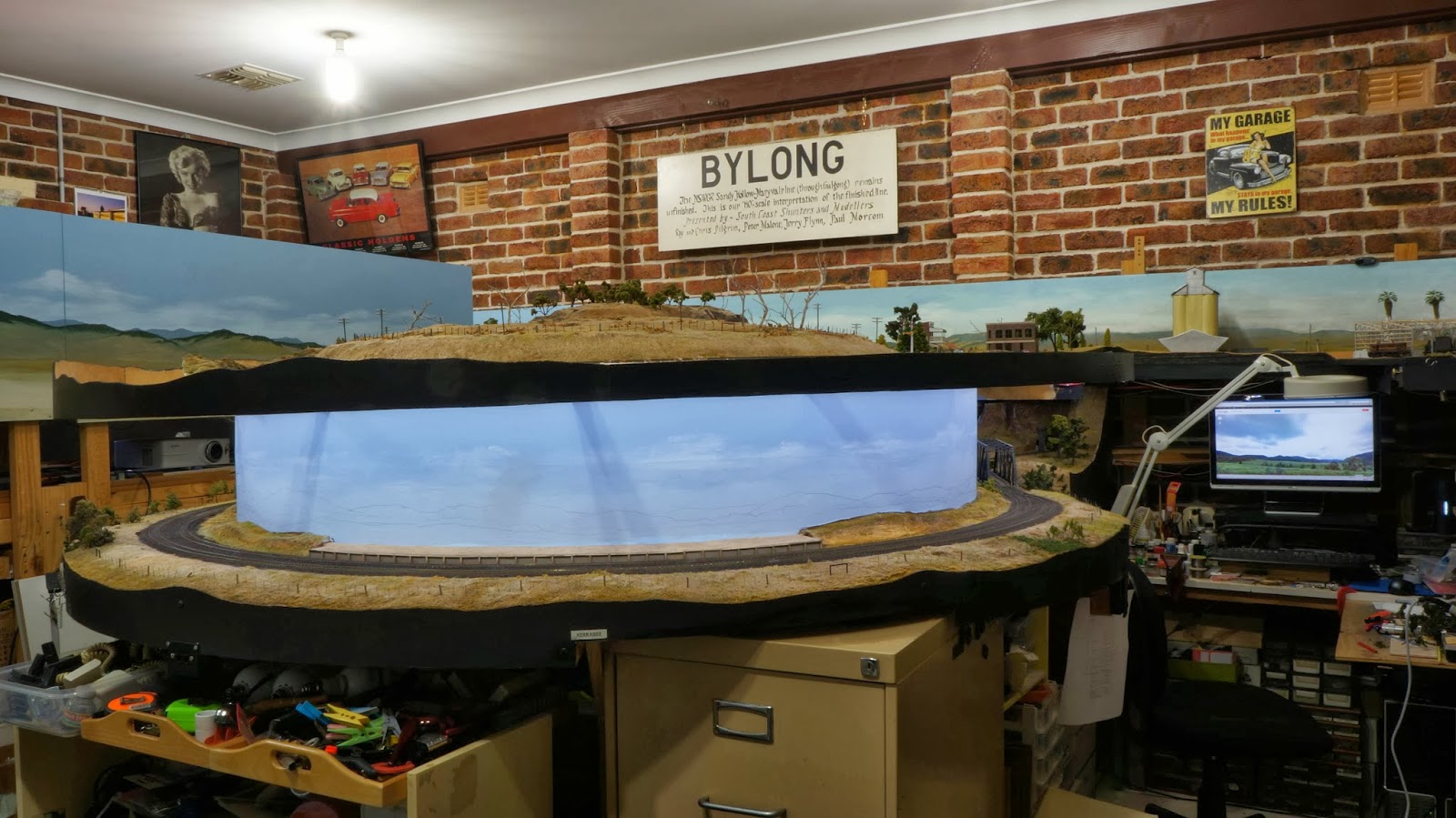
LED lighting in place.

Back scene landscape painted and basic scenery back in place.
As I like to photograph the layout I was hoping that this reconstruction would enable to me to photograph a part of the layout that was extremely difficult to do so. I have to say that I am very happy with the result and here are some trial photos I took. The photos are as taken apart from one which has had part of the lower valance removed by 'rubber stamping' grass over it in a photo editing program, it is the one which is a different shape having been clipped out of the original.

5085 on the Up Pickup crosses Kerrabee Creek

5085 on Up Pickup leaving Kerrabee

5085 on Up Pickup leaving Kerrabee

PHG guards van on the Up Pickup
Finally here is a video of the first train through the completed Kerrabee scene. Well, no layout is completed and I will be upgrading the scenery between the track and back scene in the future.


4 comments:
Ray,
Like the repairs to the lower level. The D50 sounds fantastic, what sound decoder are you using in her.
Regards
Paul
Paul
The sound decoder is a Soundtraxx Tsunami DRGW K Class, you just have to pick the best K class whistle by CV, they are all different.
Ray P
Firstly Ray, the video and photos of the locos and stock in the scene are great. The runpast is fab, I looked at it several times...it is very convincing. I love the loco. You are turning me into an aussie rail fan!
I am very impressed with the way you have utilised your space so cleverly, too...those levels are a very intriguing way to get value from the room available. I sympathise with you about the colour of LED's, in our mine exploration we use a variety of very powerful LED lights and they all have a colour cast of some sort. Sometimes it's OK, but as on our last trip, the blue is coming through too much. By the way, while I don't know much about the rolling stock in the video consist, I love the way it rumbles along and looks so convincing.
Ray
The first few shots really help me understand how to construct a fascia for my layout - I didn't even know about fascia and valances until few days back and browsing through your blog,
I happened to come across some of the best photos on how fascias are made and tie in with the layout.
Regards
Shelton
Post a Comment