Saturday, August 20, 2016

Part Missing from Fine Detail Left and Right Bracket Signals

I have just found that there was a Signal Lamp Blind part missing from the detail parts on my Left and Right Hand Fine Detail Bracket Signals released recently. The bracket signal requires two and there is only one.

The designs for both bracket signals have now been corrected.

Unfortunately, a 'guest' ordered one of each from my Shapeways Signals Branch Shop on 7 August.

As it was a 'guest' I have no way of knowing who ordered the signals and therefore who to contact about the missing part on each bracket signal.

Could the person who ordered these signals please contact me by email at rpilgrim@bigpond.net.au and state the Order Number and I will work out how to get the extra parts to them.

If you place an order on my Signals Branch Shop please register (as a designer I believe) so that I have a way of contacting you if necessary.

Tuesday, August 9, 2016

Back to Work on the Layout

I previously promised a post about the layout after a number about 3D printing so here we go.

Way back in March of 2012 I did a post on where my Cassilis branch terminus was up to construction wise. Here is the relevant post.

Well, I have started on Cassilis again, working on the track. The yard has been operating since 2012 but there were a couple of spots that occasionally would give trouble. The yard has scratch built points and I had aligned the rails, leaving a gap where it was required electrically for DCC. I used Micro-Engineering Code 70 flextrack and of course I had used track gauges when making the points. Now, I found out that the ME rail had a wider gauge than my pointwork, not by much but with nothing physically aligning the rails this was an issue.

I bought some ME insulated rail joiners and also some Peco code 70/75 insulated rail joiners to correct the issue. I had to use short lengths of the insulated fishplates so that I could lift the end on a point enough to get the fishplate on to the rail then drop the rail back down and slide the fishplate  across the gap onto the other rail. I tried the ME fishplates first and could not get them onto the first rail as the slots for the rail were very fine, too hard, so I abandoned them. The Peco fishplates have a central small vertical tab meant to keep the rails apart but as I needed a short fishplate I cut through on each side of the tab to make two small fishplates. Although a little bit fiddly these worked much better. I proceeded to do as many of the gaps in the yard as I could. Several were aligned quite well, usually between my points, so they didn't need the insulators. There were also a couple of joins that I couldn't safely raise the rails on so they stayed the same.

I followed the fishplate installation by checking the vertical alignment on the rail gaps without the insulated fishplates. Several rail joints needed a bit of shimming with some 0.010" plasticard.

After this came a spray with some light grey acrylic paint over the sleepers and rails to visually tie the flextrack with the points and their PCB and timber sleepers. If you every spray your track with acrylic paint be sure to immediately clean the track with a track rubber as the paint will go off quickly and be hard to remove if left. No, I didn't get caught with this one.

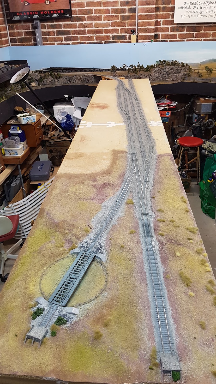
The small section of the yard at the turntable end had some scenery and the track had been ballasted with Woodland Scenics Fine Ballast Gray Blend (B1393) to imitate loco ash ballast as often used on branch lines. So knowing that I had some I went searching through my scenery materials but, of course I had used it on the branch line running from the junction near Wollar and I had very little left, a trip to the hobby shop was needed.

Ballast obtained, I spent this afternoon applying and shaping the ballast using the method I posted about in March 2012. I use an edge painter 'brush' that I found at Bunnings as shown in the following photos, dragging it lightly along the track, sweeping the ballast off the sleepers, not hard to use.

Here it is firstly showing the underside bristles.

Ballasting at Wollar - March 2012

Now in an action stance, less the copper bar weight I used to keep it upright for the photo (I take time shots and can't keep my hand still enough).


When I did the Wollar ballasting (above) I used some liquid hairspray that my hairdresser daughter had spare and it worked well but did it smell!. This time I crossed my fingers that I wouldn't get any swelling of the baseboard where three tracks cross and used water based 'glue'. The two 1800mm Cassilis baseboards are joined in the middle of the yard so I taped over the join and also a number of screws that hold the boards in alignment. I wanted to be able to find these screws if I needed to separate the two boards in the future and having the screw heads full of plaster was not a good idea, so I took this photo.


The water based 'glue' I used was Long Life Self Shining Floor Polish which is really just a thin acrylic clear sealer, basically like a thin glue. I have used this for a number of years for glueing soil, ground covers and static grass. It can be found in Woolworths in 500ml yellow plastic bottles. or you can get 5 litres at Bunnings.

So here is where I am up to.


OK, now I have to confess. I started back on Cassilis as I wanted to try out my 3D printed fishplates!

Here are a couple of views of the 4 bolt versions in place.


Now 4 bolt fishplates are usually found on sidings but can be found occasionally on the branch main so I thought I would do that. The points have different plates that appear to be the 6 bolt variety so after a bit more research I will work my way down the yard.

Apparently NSWGR had two sizes of rail, 60ft for main line and 45ft for sidings. So that means that the 6 bolt fishplates should be spaced every 60ft of main line and the 4 bolt fishplates for sidings every 45ft. Each rail joint is offset nominally by half the rail length but I am sure that wandered around a bit based on the track layout and where the rails met a set of points which would have two fishplates opposite each other. The 60ft lengths of rail would have been interesting to shift on two flat cars, probably sitting on a 'turntable' affair at the centre of each flat car. Too hard to do on a model I suspect.
If the 3D printed fishplates are placed opposite each other I have checked and they don't foul the flanges on either Code 110 or Code 88 wheels.
OK, I just checked some photos I took recently in Oberon yard and the 'main line' seems to have 45ft rail and 4 bolt fishplates joining the points and the points themselves have 6 bolt which is to be expected. So perhaps, pioneer branch lines may only have 4 bolt fishplates and 45ft rail other than on the points. And I have a branch line approximately 36ft long and that isn't counting the yard!
Who made these fishplates and caused this problem anyway ....

Tuesday, July 19, 2016

A Few Detail Parts for the Rails

I know that I promised something about what I have been up to on the layout but.....

I have recently made some 4 bolt and 6 bolt fishplates and sleeper plates available on my Signals Branch Shapeways Shop in the HO Infrastructure range and the 7mm Scale range. All of the items are printed in the Frosted Ultra Detail acrylic material.


These items were designed as a result of a request from a modeller so if you have an idea contact me and I will see what can be done.


My email address is rpilgrim@bigpond.net.au


The fishplates were designed for Code 70 and 75 rail but would also work with Code 100 rail.

The fishplates can be glued to the sides of the existing rail to add that missing detail, not for the modern image welded rail modellers though.


Of course the sleeper plates with the holes can also be used as scenic detail laying around the railway yard and alongside the line.

I have also done the fishplates just with holes for lineside details as well.

Here are some 3D renders, photos of the prototypes and a couple of HO 3D model prints.

HO Scale

Close up of 3D render of HO 4 Bolt Fishplates

4 Bolt Fishplate - Carcoar NSW


Actual 3D HO 4 Bolt Fishplate print on Peco Code 75 rail, also fits
Shinohara Code 70 and Micro Engineering Code 70 rail
Close up of 3D render of HO 6 Bolt Fishplates
Observation suggests that only 4 bolts were used.
6 Bolt Fishplate - Carcoar NSW
The 3D printed model fishplates in the photo are opposite each other instead of offset by half the rail length.
This was a test to ensure that NMRA RP25/110 and RP25/88 wheel flanges would not hit the fishplates (which they don't).
Close up of 3D render of HO sleeper plates.
The 4 holes through the plates are to fit Micro Engineering Micro Spikes (Product No. 30-108)
Sleeper Plate - Blayney NSW

Note that the holes in the actual plate are slightly off centre but the holes on the models are centred.
This is because of minimum wall thickness issues of the 3D printing design requirements.
HO 3D printed Sleeper Plates on HO timber sleeper - Code 70 Rail
Micro Engineering Micro Spikes (Product No. 30-108)

Close up of 3D render of HO sleeper plates with printed dog spikes.
Plates are designed to be slid onto Code 70 or 75 rail and glued to HO timber sleepers once gauged.

7mm Scale

Close up 3D render of 7mm Scale 4 Bolt Fishplates
4 Bolt Fishplate - Carcoar NSW
Close up 3D render of 7mm Scale 6 Bolt Fishplates.
Observation suggests that only 4 bolts were used.
6 Bolt Fishplate - Carcoar NSW
Close up of 3D render of 7mm Scale sleeper plates for Code 100 rail.
Two layers of plates are shown.
Close up of 3D render of 7mm Scale sleeper plates for Code 125 rail.
Two layers of plates are shown.
Sleeper Plate - Carcoar NSW

I hope someone finds these of some value.

Tuesday, July 5, 2016

Some more Fine Detail and 7mm Scale Signals - Offset Brackets

Just a short post to announce that I have recently made some left and right hand offset bracket signals available on my Signals Branch Shapeways Shop in the HO Fine Detail range and the 7mm Scale WSF range.

Here are some 3D renders of the signals showing the detail level. Note that these are views of the 7mm Scale signals as they show the operating mechanism below the signal base, however the HO Fine Detail Signals have the same level of detail (basically the same 3D file) but without the mechanism which needs to be ordered separately as it is in WSF to reduce the cost.

I would like to point out that these signals have two signal arms, a 39 inch and a 30 inch to allow the modeller to choose which one to use.
Overall view of the Right Hand Offset Bracket Signal
Right Hand Offset Bracket Signal platform detail

Right Hand Bracket Signal platform underside detail
Overall view of the Left Hand Bracket Signal
Note the pulleys at the base of the signal post and the small supporting brackets under the platform
Note that the large cast iron bracket is not printed in place to allow the inner surfaces
of the timber beams and underside of the platform to be painted
I have also added a left hand offset bracket to the White Strong and Flexible (WSF) original HO signal range but of course the range doesn't have the higher level of detail.

Well, that's it for now but I will get back to some posts about the layout soon.


Wednesday, June 22, 2016

A Couple of Bracket Signals and Some Ladders

I have just expanded the HO Fine Detail Frosted Ultra Detail (FUD) and 7mm Scale White String and Flexible (WSF) range of signals with a left and a right hand NSWGR Lower Quadrant tapered timber post Bracket Signal.

The HO version can be found in the Fine Detail Signals section of my Signals Branch Shapeways shop and the 7mm Scale versions can be found of course in the 7mm Scale section of the shop.

The following renders of the 3D file for the left hand bracket shows the detail I have managed to achieve. I am particularly proud of the results.

HO Fine Detail Bracket Signal
Note the see through boards and holes for wire handrails

Note the support brackets under the platform and the lamp detail

Note the wheels at the post base and the platform cast iron bracket
that is separate to allow painting inside the two timber bracket beams


7mm  Scale Bracket Signal


The same 3D design is used for both the HO and 7mm Scale signals, adjusted slightly and re-scaled.

The bracket signals come with one 39" and one 30" signal arm for a main line and a loop. As I have included the most likely signal arm sizes I will be making a range of signal arms available if different sizes/types are required.

The supporting struts attached to the HO signal post and bracket are to be removed of course, they are there to protect and support the bracket during the printing process.

To complete the HO Fine Detail signal a suitable mechanism is required and the 2 arm mechanism should be purchased. The mechanism is in WSF as it is much cheaper than the FUD material that the signal is made of. The mechanism is glued to the underside of the base of the signal.

As can be seen above the 7mm Scale signal has the appropriate mechanism as part of the print as the signal is done in WSF.

Ladders will be required and printed ladders for each scale are available.

HO 2 Ladders Sprue - FUD

HO - 10 Ladders with Cast Iron Ladder Bases - FUD

7mm Scale 2 ladder Sprue - FUD

From the above list it will be seen that I now have a sprue of 10 HO ladders printed in Frosted Ultra Detail acrylic material and these come with the cast iron signal ladder base as part of the ladder.

Apart from use with the HO Fine Detail Signals, these ladders were also designed to replace the coarser ladder of the original basic White Strong and Flexible signals if the modeller so desires or for use on other suppliers signals.

10 x HO Frosted ultra Detail Ladders with Cast Iron ladder Bases
Platform handrails are to be bent up by the modeller from brass or phosphor bronze wire as required.

Friday, June 3, 2016

The Future of the Hobby - One Man's View - Interesting

I occasionally visit a blog by Trevor Marshall who is modelling a Canadian branch line in S Scale called Port Rowan.

This post is not about his layout but I present this recent post with his thoughts on a possible direction to keep the hobby from dying away.

Trevor's post is based on a speech he gave recently at a convention and I ask you to have a read and to also read the comments at the end of his post, thought provoking, I believe he may be onto something.

Click here for the link.

There may be something here and in the comments for exhibition organisers to think about as well.

Friday, May 27, 2016

A Few Words about the 21 Pin Decoder Interface and an Interesting Afternoon

The 21 Pin Decoder Interface

Here is a well written report which backs up my ongoing dislike of this 21 pin decoder interface debacle and the growing use in Australian locomotives by some of our manufacturers.

http://www.sbs4dcc.com/tutorialstipstricks/21mtcconnector.html?utm_source=Flyer+5-25-16&utm_campaign=Backshop+Flyer%2C+160525&utm_medium=email

The only locomotive (Auscision 45 Class) I have bought that had this connector no longer has it.
The other aspect of 21 pin decoders that I don't like is that they are restricted to 4 outputs for lights, not enough by any stretch of the imagination.

An Interesting Afternoon

Linton Towelly visited Bylong yesterday afternoon with his latest ESU Loksound 4 diesel sound project loaded into a 442 Class. In my opinion Linton has taken a more sensible approach to the problem of notching in diesels.

As you may know, ESU has just announced a diesel sound flow template called ‘Full Throttle’ which attempts to replicate notching but which requires the use of about 4 more function buttons to achieve this. Given that most existing cabs have perhaps 8 or 9 function buttons available conveniently and that a number of these are relatively ‘standard’ it seems inevitable that the use of the higher number function buttons will be required, hence the awkwardness of using it. Of course, I have previously referred to the manual notching of ESU Loksound 4 diesel sound flow templates as playing a musical instrument and I believe now that with ‘Full Throttle’ the instrument has become a piano.

One good aspect of the ‘Full Throttle’ sound template is that it now has a working brake.

Now back to Linton’s sound flow template. Linton downloaded the new ESU ‘Full Throttle’ sound template for an EMD 645E for his NSWR 422 Class and then proceeded to remove the diesel motor sound drive flow chart that controls the notching but retaining the other aspects such as the braking.
Linton has previously produced a sound flow template for a XPT which has only 5 notches.

Expanding and modifying this template Linton has produced an eight notch template as used by most diesels. When Linton deleted the sound flow for the motor drive this action didn’t delete the sound files of the motor so he was able to use these in his motor sound drive flow.

The end result is very nicely implemented and although I haven’t driven a diesel (Linton used to drive them) I feel that his implementation seems to be much more like the real thing than the new ESU ‘Full Throttle’.

Now how does it work?

When the throttle is increased the diesel motor sound starts to notch up and will continue to notch up until it reaches notch eight unless the throttle setting is reduced by 1 speed step at which point it will hold at the particular notch running when this throttle adjustment happens. If the throttle is then reduced again by 1 speed step the diesel motor will start to notch back down. If the speed step is increased the notching will increase to the previous level and another speed step increase will have the notching increase again until of course it gets to notch eight. Now keep in mind that this may happen at very low speed steps, e.g. 2 or 3 which means that the loco can be put into notch eight while hardly moving (heavy train). The same actions at higher throttle speed steps can produce the same effects meaning that once moving at a good speed the throttle can be reduced slightly and the diesel motor sound will drop back into a coasting phase. All this can be achieved without hardly changing the actual moving speed of the locomotive and just by using the throttle, no function buttons to remember, find and press for different aspects of the ESU ‘Full Throttle’ implementation.

I should have taken a video of the 422 in action going up and down the 1 in 40 grades on Bylong with a full train but I was having too much fun driving it and didn’t think of doing a video. Linton designed this motor drive sound flow chart using 28 speed steps but tests on Bylong showed that it also worked on the 128 speed step range of the throttle.

For those who haven’t seen the videos, here are two videos that Linton posted on a couple of Facebook groups recently in which he explains what he has achieved. You may need to turn up the volume a bit.

I hope that I have explained the way Linton’s notching works correctly but I think that you will get what I mean after watching the videos.

Part A: https://www.youtube.com/watch?v=s7TZyMN3iJQ&feature=youtu.be

Part B: https://www.youtube.com/watch?v=YQFEI5s4FnE

In the Part B video there is also an explanation of how Linton has the dynamic brake working, very nice. The dynamic brake doesn’t actually brake the locomotive speed though but it does go through all the sound changes that the real diesels do, of course the working brake could be used to replicate some actual braking I guess.

Overall a very enjoyable and interesting afternoon with Linton.