Monday, November 9, 2015

A Bit More Architecture - Werris Creek Station Building Again

A while ago I tried to restart construction of the Werris Creek station building for Ron Cunningham's Werris Creek layout and realised that I hadn't etched enough awning post cast iron support brackets Also, given that I had etched them at home the consistency of the etches wasn't that good.

I sat down at the computer, fired up Sketchup and spent several hours drawing up the bracket. The following photo of the brackets and a screen grab show the result. The brackets now had some thickness and edge flanges around the fancy bits, much better. Due to wall thickness design minimums for the Frosted Ultra Detail material I had to do some creative drawing to get more of an impression in places by impressing some detail rather than cutting through. Over all, although it isn't as fine or airy I was very happy with the resulting 3D model. The GNR didn't come out and this was probably because the height of the letters wasn't enough and the height is restricted as there is a ratio of height to width where the letters would become a wall and they would fail the minimum wall thickness test.


Rear of the brackets showing some fine lines caused by the support material used in the printing process
Other side of brackets, nice and smooth
I had originally etched the cast iron detail in the end of the awning as well so I decided to give it a go as well and this one I am very pleased with as being larger the wall thickness design minimum wasn't a real issue.
 
 
The lower awning end is for the awning on the other platform
3D printed Frosted Ultra Detail awning end
As can be seen, by using 3D printing I was able to also make the whole awning end rather than having to construct it from Evergreen polystyrene strips and shapes.

I am now at the stage with the build where I can offer the awning up to the building although I still have to add the smaller downpipes and scuppers that I had to rescale before I can fix the awning permanently.

I haven't quite finished the awning itself as I still have to fit the corrugated iron and there are 4 foot (1200mm) single fluorescent lights on the awning rafters between each post as shown in this photo.


So here we have some HO single tube fluorescents that will take a 603 Cool White SMD LED (with leads). The LED fits into a hole in the middle of the base and the wires exit the end closest to the wall to be connected to a resistor and power inside the building. The light base will be painted black and then white to try to restrict the LED light to just the tube but I am sure that it will mainly be in the centre of the tube. I am not sure how else it could be done given the restriction of the size of the base and the minimum wall design thickness.

Top

Base showing LED location and wire slot
But, there is more.

Mounted on the building as well as scattered around the platform on posts are some hooded double fluorescent lights so I have done these as well.


Here are screen grabs of the top and the bottom of the lights. The double fluorescents go inside the hood with the 603 SMD Cool White LED placed inside and the wires threaded through the hole in the end of the hood. The hole in the end of the hood and the wire slot are large enough to have a piece of 1mm plastic rod or 0.035" phosphor bronze wire (be careful here don't damage the LED wires) inserted to be used as the tubular mounting shown in the above photos.

Top
Base

Here is a photo of the 3D print, as the Frosted Ultra Detail (FUD) is translucent prints are very hard to photograph.


Well, the above have been some of the distractions I have been involved with trying to overcome the loss of our beautiful daughter earlier this year. The problem I have is completing things but I am sure that it will all come together.

On another architectural note, a comment was posted on my recent architectural post asking about cast iron lace work and panels for terrace buildings, pubs, etc. I have had these on my list for a while and do have some photos/artwork that I can work with. The problem is that a lot of the lace work is very fine and the minimum wall thickness issue will raise its head. So only certain designs will probably work. These will take some time as the conversion/tracing of the lace work and the adjustment for wall thickness is quite involved, there is also the question of how long a length of lace work panels, etc. should be designed.


Monday, November 2, 2015

A Little Bit of Architecture

OK, not architecture in terms of whole buildings but a few bits I have been working on.

A while back I was in need of distraction to keep my mind from other things and I find that the problem solving that is required for drawing up 3D items is just the thing to keep the mind occupied.

I decided that I would have a go at drawing up some corrugated iron, firstly to see if it could be done effectively and also out of interest to see how much it might cost to have printed.

I managed to track down some cross-section drawings of  'standard' corrugated iron and using this as a starting point I imported the line drawing into Sketchup as a JPG image. I then traced the cross-section and proceeded to turn it into a 3D representation within the limits of Shapeways Frosted Ultra Detail material. I had decided that the White Strong and Flexible material wouldn't give a nice smooth surface and anyway the wall thickness design minimum precluded it from the project.

Here is a picture of a print that I have had done. I had this printed to see what it looked like and to get an idea of the price, unfortunately nice as it is the price is expensive compared to available HO corrugated iron. The sheets are 10 feet long and 22 1/2 inches wide which is the visible size of a sheet of iron that has a one and a half corrugation overlap. The idea is that each sheet will but against the next on a suitable modelled timber framework or sheet of plastic and the edges of the sheets will be seen as the joint between sheets. The printed sheets are only 0.42mm thick.
 

I have since added more supporting sprue instead of the single sprue down the centre. This is to ensure that nothing will be broken off in the cleaning process after printing. The problem is that Shapeways staff don't know what a particular print is so if something breaks off, the print is rejected even if it doesn't matter to the modeller. Of course some printed bits left loose after the cleaning can't readily be identified with a particular print order.

Since the print was acceptable I then moved onto something that I had been thinking about for years, bull nose corrugated iron. Bull nose is a challenge due to the difficulty of rolling the curve to the right radius and to do so without putting a kink in the corrugations. It was also a challenge to draw, here is the result.


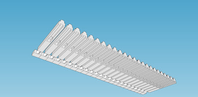
Now, where to from here? I was telling a friend about what I had been up to when he asked, "What about decent guttering?" I promised that I would give it a go and send him some, so this was next. Back to find a  suitable gutter cross-section from years ago (1930's, 40's, 50's, 60's, 70's, etc.). I knew that wall studs and roof rafters were spaced at 18 inches (450mm) in older houses and that gutter support brackets were usually placed on every second rafter end so this is what I drew up.


 And I then added sprues to give 4 x 30 foot lengths for printing.


Here is a photo of the printed gutter which I have darkened in an attempt to make the support bracket detail, etc. show better. The guttering print price looks good.


I am currently waiting on a print of a corrugated water tank which price wise at least is viable, here is a computer render of the tank and it has the correct corrugation cross-section.
Well, that is about where I am at with these items and I have decided that I will put them all on my Shapeways Signals Branch shop, someone might be rich enough to want to use the corrugated iron sheets, who knows. I am also making them available with the long term hope that the cost of printing will come down so that I can reduce the price.

Now I just have to find a nice building to make so that I can use these bits.